Torus networks are frequently utilized on top-performing supercomputers. They have certain drawbacks, but their main benefit — cost — makes them appropriate for very big installations. Besides, in some computational algorithms compute nodes mainly exchange data with their closest neighbours, and in this case the torus topology nicely coincides with the algorithm.
On this page you will find description of how torus networks are made (including a sample cable layout), as well as a link to the web service that allows to design torus (and fat-tree) networks automatically.
I am brave and bold, get me right to the tool!
Paper folding exercises for the absolute beginners
Torus (plural “tori”) is a shape that resembles a doughnut. How comes that this term is used for computer networks?
Let us take a look at this example. Take a rectangular sheet of paper and draw a grid on it. Place the computers that you want to communicate on the intersections of this grid. The grid lines will represent your communication links. As you can see, a computer in the upper left corner cannot easily reach its friend in the lower left corner: the packet will need to travel through the entire grid, to its bottom.
But you can add another communication link that goes directly to the bottom computer. It may seem that it will be longer than all other links on your grid, but try to fold your paper in a tubular shape, so that the top and bottom edges of your sheet are aligned, and you will see that the two computers mentioned above are now very close (imagine that you sew two edges with a short thread, that will be your new link).
This link tremendously decreases communication latency for the computers that have just been so far away from each other. But this single link, although a time-saver for packets travelling to “another edge” of you paper, would quickly become overused. So, to make things better, you can add multiple links to connect the two edges — from every computer in the top row to its mate in the bottom row.
Now, remove the thread (if any), unfold your paper and put it back on the table. Consider the same computer in the upper left corner, but now it wants to communicate to the computer in the upper right corner. Again, a “normal” travel would require the packet to follow along the upper edge of the paper. But what if you fold your sheet again in a tubular shape, this time aligning left and right edges? The two computers are again very close, and you can add a link to connect them directly. And, just as in the previous case, to gain a better bandwidth, you can add many links that go from the left edge of your paper to the right edge.
Unfold everything back and think for a minute. Could you do both optimizations at the same time, and fold the sheet in both directions simultaneously? The answer is yes, although somewhat counter-intuitively, because paper is not the best medium to demonstrate this. We would need something that stretches well, such as rubber. The first step is to make a tube from your sheet. Then, you need to connect both ends of the tube, and this is where stretching becomes necessary. The result is… a torus — hence the name for these networks! Take a look at this animation from Wikipedia; it is amazing:
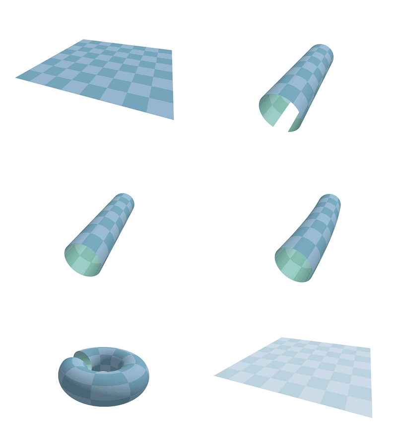
Torus from rectangle. Animation by Wikipedia user Kieff. Source: Wikipedia Commons.
That’s how a 2D torus is made. In real life, you don’t need to distribute your computing hardware on the vertices of a giant doughnut. Instead, it sits in racks on the floor of your computing room, as with any other network. And longer cables are employed whenever you need to reach remote computers, just as you would need a longer thread if you tried to connect two edges of your paper sheet without folding it into a tube. (We will take a look at a possible cable layout in the example below).
How a 3D torus is made?
Still not tired with paper exercises? Suppose you use cotton threads for the long wrap-around links on your flat paper mock-up. That won’t look very neat, but we don’t care. How many computers do you have in each of your two dimensions? Suppose it is N in a horizontal dimension, and also N in a vertical dimension. Remember: an ideal torus network is the one which uses the same number of nodes along each dimension, otherwise the network becomes imbalanced. Your 2D torus (although lying flat on a table) connects NxN compute nodes.
Now, make N analogous paper mock-ups, and place them all in a stack on your table. Start with the left upper corner. Sew them together, through the compute node, perpendicularly to the surface of the table, and when the needle exits the stack from behind, pierce the stack again in the opposite direction using an “empty space” between compute nodes, thereby bringing the thread to the node where it started. Then, do the same with all NxN nodes. That’s how a 3D torus is made. It can connect NxNxN nodes. If N=10, then you can connect 10x10x10=1000 nodes. That’s a pretty big compute cluster!
I hope you don’t perform this exercise in practice, because there are better ways to visualize a 3D torus. One of the best renderings I have ever come across is the one by Fujitsu, made to demonstrate the network they thought would be utilized for the K Computer in 2012 (however, K Computer used a much more complex “6D mesh/torus network”, as Fujitsu terms it — watch the video here).
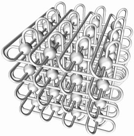
3D torus rendered by Fujitsu. (c) Fujitsu and RIKEN, 2009. Source: press release.
As you can see, in a 3D torus every compute node is connected to six neighbours. And nodes located on the “edge” of the torus are still connected to 6 neighbours, simply they use long wrap-around links.
The main motivation for more dimensions in a torus is to maintain a low latency when connecting a big number of nodes. For example, if you wanted to connect N=1000 nodes with a 2D torus, you would need a 32×32 grid. If computers are exchanging data in a random fashion, then the average distance the packet has to travel on such a grid to reach its destination is larger than could be achieved with a 10×10×10 cube. From the upper left corner of the grid, the most remote destination is in the centre of it. On a 32×32 grid, you would need to make roughly 16 steps to the right, and then 16 steps to the bottom, to reach the centre of the grid — that is 32 steps in total.
With a 10×10×10 cube, to reach the centre from a vertex, you need to make 5 steps in one direction along the edge, 5 steps in the perpendicular direction, reaching a centre of the cube’s facet, and finally 5 steps down into the cube — this is only 15 steps, compared to 32 in the previous case. More steps means bigger latencies, which is very harmful for parallel computations. That is why big supercomputers use 5D (such as IBM Sequoia) or 6D tori.
To use switches or not to use?
There are two approaches in the computing industry to building torus networks. The first approach puts compute nodes into the “lattice” of your torus. Circuitry inside network adaptors of compute nodes then takes care of forwarding packets that flow through the network. No dedicated switches are necessary (that’s because every network adapter is a small switch by itself). Such networks are called “direct networks”, because compute nodes directly connect to each other, without any switches in between.
For 2D (two-dimensional) torus networks, you need a network adaptor with four ports, connecting your node to four neighbours. For bigger 3D networks, there are six neighbours, so you need a network adaptor with six ports. Examples of this technology are (1) SCI adaptors made by Dolphin (this is an outdated technology), and (2) EXTOLL adaptors designed by the research group of Prof. Dr. Ulrich Brüning and marketed by EXTOLL GmbH (a very recent technology).
A considerable benefit of this approach is that the switching elements of the network can be brought as close as possible to the place where the data to be transferred originates — the CPU. With EXTOLL technology, network adaptors are plugged in into a HyperTransport bus via an HTX slot on the motherboard.
But there are drawbacks as well. If you have a network adaptor with six ports, this means that six cables will connect to each compute node. Cable connectors do take up space (and it is difficult to make them any smaller), so with the trends to miniaturization, six cables is perhaps the current technological limit for commodity hardware.
Even connecting one copper InfiniBand cable to each ordinary rack-mounted server creates a cabling structure that can obstruct airflow. Six cables is just too much. Consoling is the fact that two of these six cables will run to a very short distance — namely, to neighbouring compute nodes just above and below the node in question — so they can be made somewhat thinner than the remaining four. Or you can use optical cables which are thin but costly.
Happily, there is another approach to building torus networks, and it doesn’t require you to route thick bundles of cables into the compute nodes. Instead of placing compute nodes into the “lattice” of your torus, you can place network switches there. Those ordinary network switches, e.g., InfiniBand switches with 36 ports. Compute nodes then need to have ordinary network adaptors, and packet forwarding will be done by the switches. Such networks are called “indirect”, because compute nodes connect to each other not directly but via switches.
This has certain latency implications, because in order to get to the torus network, the packet has to pass through the network adaptor and then through the switch, while in the previous scenario there was only one device — the network adaptor that also acted as a switch — instead of two. The same applies to the receiving side. So, if latency is important for your applications, you may wish to refer to benchmarks and choose the technology that would provide you with the right balance of latency and cost. (And if the lowest latency must be achieved at all costs, why not to try ye olde fat-trees? But I digress…)
One and only one cable needs to run from a compute node to a switch — although you can have more if your compute node needs more bandwidth. This way, you can connect 18 nodes to a 36-port switch. The remaining 18 ports of the switch will be connected to its neighbours — in a 3D torus network, to 6 of them — a bundle of three cables to each neighbouring switch. Take a look at this presentation by Todd Wilde of Mellanox Technologies, filmed by Rich Brueckner of insideHPC.com, or get the slides in PDF from the HPC Advisory Council website.
An example of cable layout
Let us consider a computer cluster made with Hewlett-Packard blade servers and design a torus network for it. Blade servers made by Hewlett-Packard can vary widely in their prices, depending on what components you put inside. But suppose you identified a particular server model that you wish to use — say HP BL465c G8 — and its configuration, and your budget allows you to buy 180 blade servers (with top-performing CPUs that is roughly $2M, by the way). You put blade servers into HP BladeSystem c7000 enclosure (also called chassis), and each chassis accommodates 16 servers. Therefore, you need 180/16=11,25=12 chassis.
On the back side of the chassis there is an interconnect bay where you can insert an InfiniBand switch. It has 32 ports. Of them, 16 ports become electrically connected to network adapters in the blade servers as soon as you insert the switch. This type of connection is much more reliable than using cables for rack-mounted servers. The remaining 16 ports of the switch are visible to the user, and you can connect cables to them like you would to any other switch. We have 12 chassis, which also means 12 switches. We will build a 2D torus network with dimensions 3×4 (because the 6×2 torus is imbalanced, and even more so the 12×1 ring, which is the degenerate torus).
In a 2D network, each switch has four neighbours. Therefore, the 16 ports of a switch will be equally distributed — 4 ports to each of 4 neighbours — and cables to neighbours will run in bundles of four.
A single chassis takes 10U, so in a standard 42U rack we can place four chassis. We are very lucky here, because our torus is 3×4 (or 4×3, it doesn’t matter), and we can use four chassis in a rack as one dimension of the torus (we’ll call this “y” dimension, because chassis in a rack are stacked vertically). The three racks provide another dimension, which we will call “x”, because racks adjoin each other along the horizontal axis. Therefore, let us refer to our topology as a “3×4”.
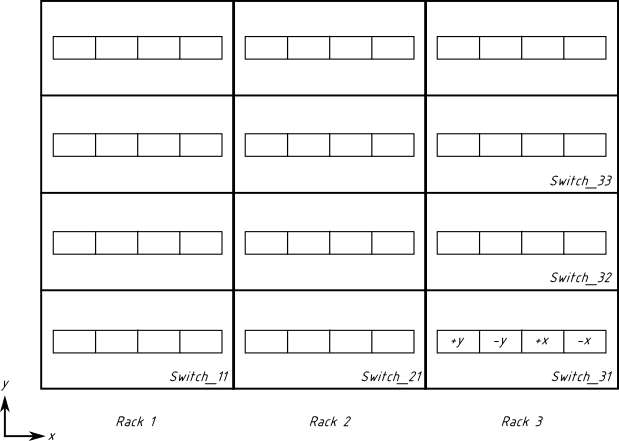
We will use the advice given in Todd’s presentation and choose a pattern for switch names and ports (slide 13 of the presentation). I only chose to start counting switches from ‘1’, not from ‘0’, as we do with ports and racks. There will be two dimensions — x and y — and 16 ports of each switch will be divided into four groups:
+y: 1, 2, 3, 4
-y: 5, 6, 7, 8
+x: 9, 10, 11, 12
-x: 13, 14, 15, 16
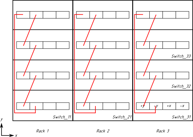
Below is the graphical representation of our three racks (view from behind). Each rack houses 4 chassis. Every chassis has one switch. 16 ports of each switch are divided into four groups (see Switch_31 for details). Drawing is not to scale (actual 42U racks are higher than shown).
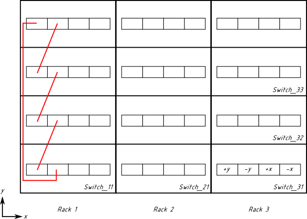
Let us start wiring in the y dimension, because it is simpler. When we go forward (y increases), we use switch ports from the group “+y”. Cables go from group “+y” to the next switch in sequence, to its group “-y”. Here is the first loop of our torus:
Verify that cables go in the “+y” → “-y” pattern, e.g., from group “+y” on Switch_11 to group “-y” on Switch_12. What is especially good is that this cabling is completely within the rack. It doesn’t go to the overhead tray or to other racks. It is independent in all three racks. We do it analogously in the other racks:
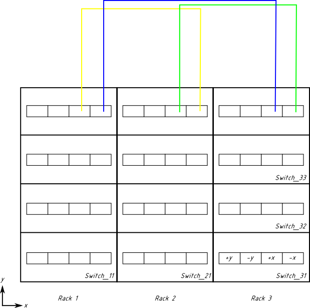
Now, we are done with the “y” dimension. Let us proceed with the “x” dimension. The difficulty is that this time cables have to go from one rack to another, and if you just pull them from, say, Switch_11 to Switch_21, the rack’s doors won’t close, therefore we need to use the overhead tray. This requires significantly longer cables, especially for the chassis located in the bottom of the rack. Let us start with the top switches.
The order of cables is yellow, green, blue. Verify that cabling follows the “+x” → “-x” pattern (i.e., the yellow cable goes from “+x” on one switch to “-x” on the next one).
Note also that the cables are schematically shown to go straight up, whereas in the real air-cooled installation you would choose to align them with the side of the rack, so that they do not obstruct airflow. And you would likely choose the right side of the rack for that purpose, because the left side will be probably used by our cabling in the “y” dimension (not shown, but still there).
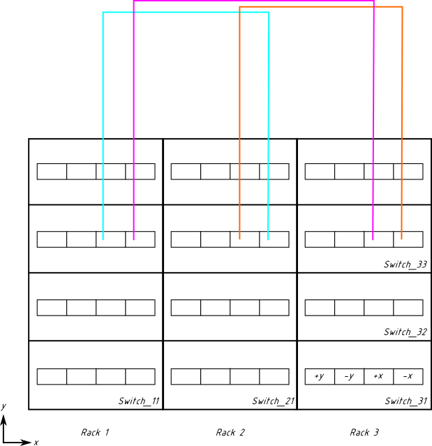
The next row of switches is cabled similarly (previous cabling not shown as not to clutter the image):
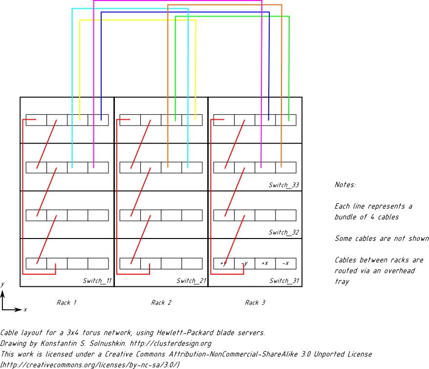
Now you have to connect two bottom rows of switches in the similar way, and you are done. If we try to depict all cabling done in the previous sections, it will look like this:
Congratulations! You have successfully designed a 2D torus network for 180 nodes. (If you wish to experiment with the drawing, feel free to download the SVG file, best opened with Inkscape).
Torus networks are inherently cheaper than fat-trees. Indeed, if we tried to design a fat-tree for 12 blade chassis, then switches in the chassis would act as edge switches, and we would need a separate set of core switches for the second level of the fat-tree. Therefore, the fat-tree would be more expensive. At the same time, it would provide low latency and non-blocking bandwidth. (In fact, if you factor in the cost of compute nodes, the fat-tree doesn’t seem that expensive).
Expanding torus networks
Fat-trees can be easily expanded if you properly design their core level from the beginning. But what about tori — how can we expand them? The traditional approach is to stretch them along one of their dimensions.
With the above example, we could leave the cabling in the “y” dimension as it is (red wires, independent in each rack), and stretch in the “x” dimension. We would add as many racks as necessary, and make sure that on the border of the old and new racks, the long wrap-around links (blue and purple on the figures above) would not return to Rack 1, but would instead proceed to Rack 4. Eventually, from the last Rack N, there would be a wrap-around link back to Rack 1.
If the wrap-around link from Rack N to Rack 1 is getting worryingly long, use the cabling recipe on slide 13 of the aforementioned presentation. This way, all cables will be slightly longer, but none of them will be exceptionally long.
This traditional way of torus expansion can lead to imbalanced networks. How do you like a 100×4 torus? There are two conditions that must be met in order for such a structure to be functional:
1. Your computational code must exhibit locality of communications. Otherwise, packets from one compute node to another will need to pass through all intermediary switches. Those switches are already busy with other tasks (which reduces bandwidth), and there are many of those switches (which increases latency).
2. The other condition is even more difficult to fulfil: your job scheduler must be topology-aware, so that it schedules all processes of a job in the same part of the torus (in fact, this condition is also essential even for balanced tori). If you know job schedulers that explicitly support torus topologies, please drop a comment. (Update from November 2012: MVAPICH2, the MPI implementation, is now topology-aware).
To make the long story short, you can’t build a 100×4 torus and hope that it just works. You need to stretch it in the other dimension(s) as well. With the above example, you could make a 20×20 torus instead of 100×4. (A 3D torus with dimensions 7x7x8=392 would be even better, but you will need to re-cable everything).
Our vertical dimension — “y” — was equal to 4, and we now want it to become 20. The “y” dimension is wired with red cables on our figures. Normally, it spans 4 chassis, that is why it is equal to 4. If we want it to be equal to 20, we need to span 20 chassis — that is, 5 racks. To make cabling simpler, we need to add another row of racks behind our original row, and then another one, and so on, until we have 5 rows.
Now, rewire red cables: from the upper chassis in the rack in the front row, it should go to the second row of racks, pass through all chassis in that rack, follow to the third row, and so on, until all five rows are embraced — and then return to the front row.
Sounds complicated? Yes, it is, but proper planning of future expansion will simplify things. Besides, HPC installations are rarely expanded by more than twofold, therefore stretching in one dimension could be enough for your purposes.
Automated design of torus networks
If you need to quickly design a torus network, you can use the web service linked at the bottom of this page. It can design fat-tree and torus networks, giving you quick approximations of network cost, power consumption and other metrics, as well as the bill of items you need to buy. The tool will automatically choose a suitable number of torus dimensions for you.
Conclusions
- By using commodity InfiniBand hardware, you can easily build torus topologies for HPC installations — and for data centres in general!
- Network switches take care of all routing complexity. Switch and cable failures are handled automatically.
- Torus topologies are cheaper than fat-trees for the same number of compute nodes. However, if you take the cost of compute nodes into account, the price difference diminishes.
- Future expansion is possible, but requires planning in advance.
The tool –> Fat-Tree and Torus Design Tool
To download the tool, proceed to the “Downloads” section.

Pingback: To the Moon | How to JBoss
Pingback: Visualizing software defined network topologies using POX and Gephi | Open-Source Routing and Network Simulation